4W调频发射电路图
4W调频发射电路图
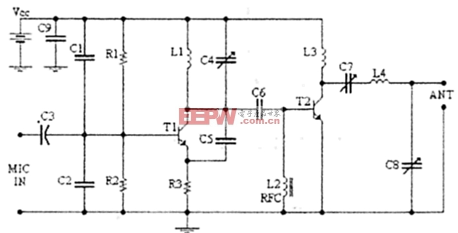
TECHNICAL CHARACTERISTICS:
Stabilised tendency of catering: Vcc=12~16V
Frequency of emission: 88~108MHzConsumption: 100~400mAMaterially:
The resistors are 1/4W.
R1, R2
10KOhm
R3
47Ohm
C1, C2
1nF
C3
4,7uF/16V
C4, C7, C8
0~45pF trimmer
C5, C6
10pF
C9
100nF
L1
4 turns, 7mm diameter *
L3
3 turns, 7mm diameter *
L4
5 turns, 7mm diameter *
L2
RFC (resistance 1MOhm with wrapped around her inductor of enough coils from fine isolated wire. Scratch of utmost inductor and you stick in utmost the resistance making thus a parallel L-r circuit.)
T1, T2
2N2219
ANT
Simple dipole l/2.
MIC IN
Microphone dynamic or other type. (It can also connected to a cassette player unit)
* The inductors is air from wire of coaxial 75W or other 1mm roughly.Regulations:
With the C4 we regulate the frequency.
With their C7, C8 we adapt the resistance of aerial (practically to them we regulate so that it is heard our voice in the radio as long as you become cleaner).
Notes:
The T2 wants refrigerator.

加入微信
获取电子行业最新资讯
搜索微信公众号:EEPW
或用微信扫描左侧二维码