声音闪光警告电路
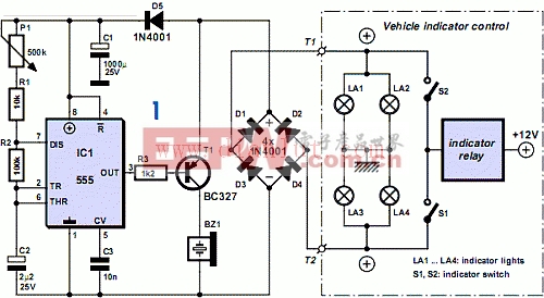
The output of the 555 is active Low, meaning that initially the transistor is blocked and the sounder is silent. The timer always charges and discharges capacitor C2 to a level between a third and two-thirds of the operating voltage, producing an interval of 0.7 x C2 x (R2 + R1 + P1) [s] The preset enables you to set this delay up to a second or so. The initial delay, before the sounder first operates, is significantly longer, however, because the electrolytic has zero charge. Only after this delay is the output active, for the pulse duration of 0.7 x C2 x R2 (equivalent to about 0.15 seconds), enabling the sounder to operate.
This applies only when +12 V is present at the collector of transistor T1, which is the situation when the flasher relay is just switched on and the indicator bulbs light up. The circuit is built inside a splash-proof enclosure, installed on your machine in a position that’s out of harm’s way. The audible sounder can be positioned anywhere outside the enclosure if it’s a waterproof type. The audible control unit requires only two cable connections, which can be made at any convenient access point.

加入微信
获取电子行业最新资讯
搜索微信公众号:EEPW
或用微信扫描左侧二维码